I purchased 6x 9Ah 18V non-genuine Makita batteries to power the billycart I built. After their first charge and then use one of them would not charge past 1 bar on its gauge or 17.35V instead of 20.5V.
THIS IS STILL BEING WRITTEN SO PLEASE CHECK BACK FOR UPDATES

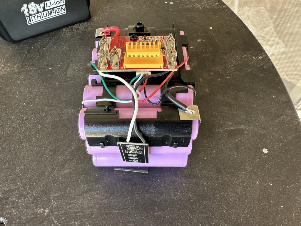
I went through the cells and measured the voltage of all the cells, which are in 5S3P configuration. 1=4.14V, 2=4.12V, 3=0.81V, 4=4.12V, 5=4.14V. Turns out the 3rd set of cells was down to 0.81v. I tried them charging it, which did eventually charge up to 4V , but then started self discharging.
I then isolated the 3 cells to try to locate the faulty cell, but after measuring them all and trying to recharge 1 it turns out they are all non-functional. I suspect 1 died, then the others were reverse charged when the battery pack was discharged,which would have killed the other 2.
I then contacted the EBay seller to request a replacement battery which they said would be a fortnight away.
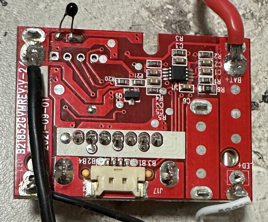
Now that I had a battery apart I thought I would look at the batteries and the controller board
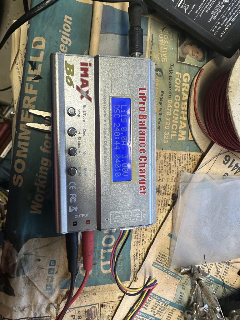
Being a 9Ah battery, each set of parallel cells should have at least 9Ah of capacity. I tested the first parallel battery set for capacity by discharging down to 3V.
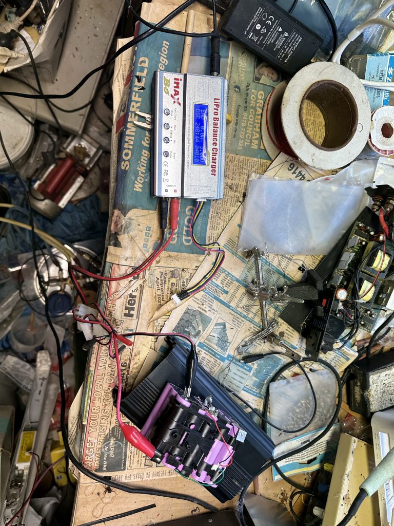
I discharged the cells with an iMAX B6 copy at a 1A discharge rate expecting a capacity of at least 7Ah, or 2.5Ah per cell. The result was a dismal 4Ah
A charge up to 4.1V showed they accepted 3.6Ah, which it would have accepted a little more but the 12 hour timeout stopped it prematurely, also telling e the cels have a relatively high internal resistance if the Constant Voltage (CV) stage of the charge cycle takes that long.
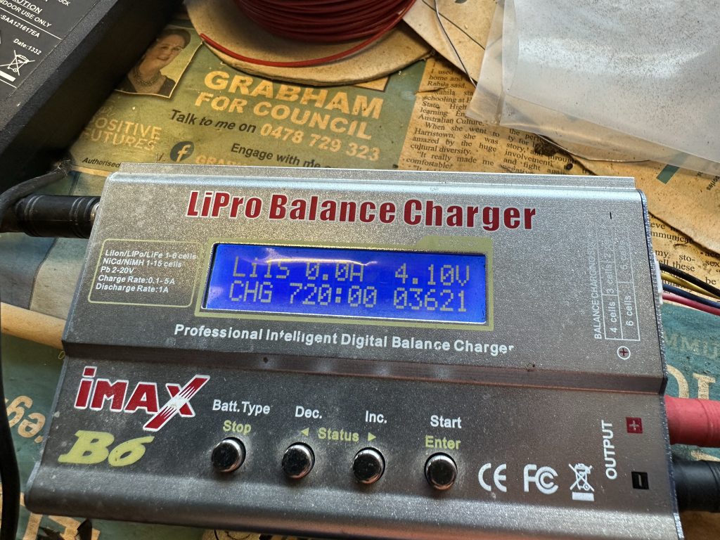
So not only is it faulty, but it is also fake. I will test the other 5 batteries shortly and the 6th if it arrives.
The main PCB has 2 chips on it. 1 is communicating with the charger to allow it to charge and the other is a battery balancer.
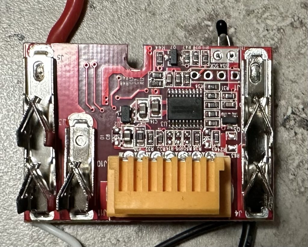
The battery balance IC is designed for 3-5 cells and can had variants for different voltages ranging from 3.8V to 4.4V with different hysteresis values. The one I have has a over charge threshold of 4.250V and a hysteresis of 0.1V, bringing it down to 4.15V
The charger controller ic is a 8 bit integrated controller. I found the below specs here https://bbs.16rd.com/thread-572600-1-1.html
GVM08x003 is an 8-bit wide-voltage MCU for high-speed IO applications, with built-in high-speed SPI module and high-speed I2C module for low-cost and high-performance communication processing applications.
Features:
1. High-performance 8Bit core
8Bit1T enhanced 51 core, instruction code compatible with standard 51
operating frequency up to 64MHz The
peripheral module clock is a separate gated clock, and the user can selectively turn off the module clock to reduce dynamic power consumption; At the same time, each functional module can separately configure the enable signal
in the ROM Support a total of 13 interrupt generation sources, 4 levels of interrupt priority control.
2. Memory
On-chip integrated 256 BytesS RAM as internal data storage area
On-chip integrated 1K BytesXS RAM as extended data storage, can also be run as a program.
On-chip integration of up to 16K Bytes FLASH as program memory
On-chip integration of 2K Bytes NVR (non-volatile register) On-chip
integration of 2K Bytes ROM as the chip’s BootLoader and self-detection (boot boot block).
3. Multiple clock sources, there are 4 sets of clocks to choose
External clock CLKIN/XTAL, up to 24MHz clock input
internal low-speed FLIRC Internal high-speed FHIRC Internal FHIRC internal FHIRC
divider (default 4 divide-by), 32 gears can be configured
4. Working mode
Wide working voltage 2.7V~4.25V
Working temperature -40°C~85°C
4 working modes, NORMAL mode, IDLE mode, STOP mode and DPD mode DPD mode
quiescent power consumption as low as 0.5uA, IO wake-up and reset
Specification differences
GVM08x003 is divided into GVM08F003 (basic type), GVM08L003 (low power type), and GVM08H003 (high performance type) according to the system clock frequency and power consumption, the main differences are shown in the following table:
| difference | GVM08F003 | GVM08L003 | GVM08H003 |
| System highest frequency (FHIRC) | 40.55MHz | 40.55MHz | 64MHz |
| Internal low-speed oscillator frequency (FLIRC) | 128kHz | 128kHz | 128kHz |
| DPD current | 5uA | 0.5uA | 0.5uA |
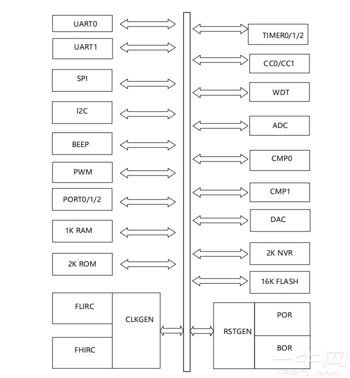
Logic block diagram:
Register distribution
The GVM08x003 special function register consists of three parts: CPU-specific register, extended control register and secondary decoding register, as shown in the following table. The address of the special function register is 3x0H~80xFFH, which overlaps with the internal data memory address, and the direct address addressing is used to access the special function register, and the indirect address is used to access the internal data memory. Visiting an undefined region will yield unpredictable results.