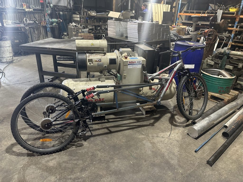
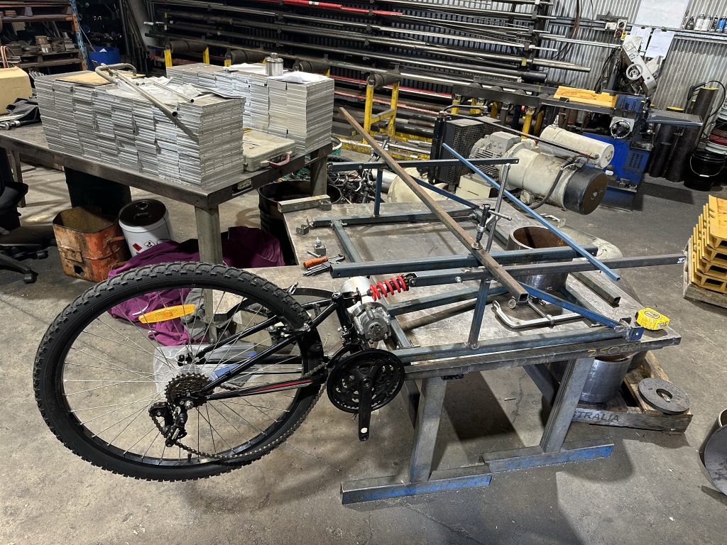
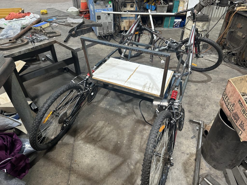
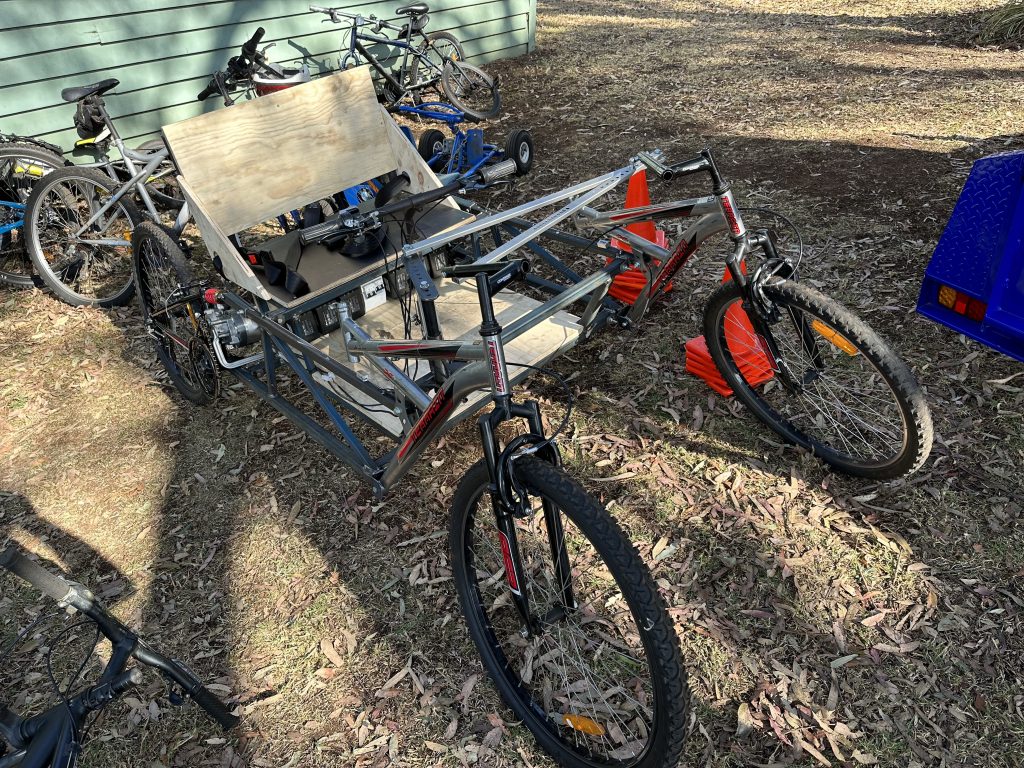
I wanted to make a new downhill billycart for Space Pilots camp that I didn’t have to push up the hill. Unfortunately that didn’t happen this year, but I did make an awesome attempt that will need to finished before next year.

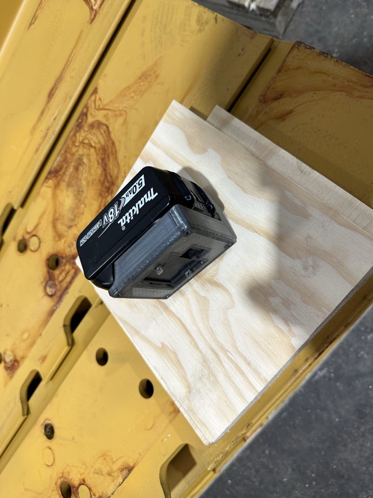
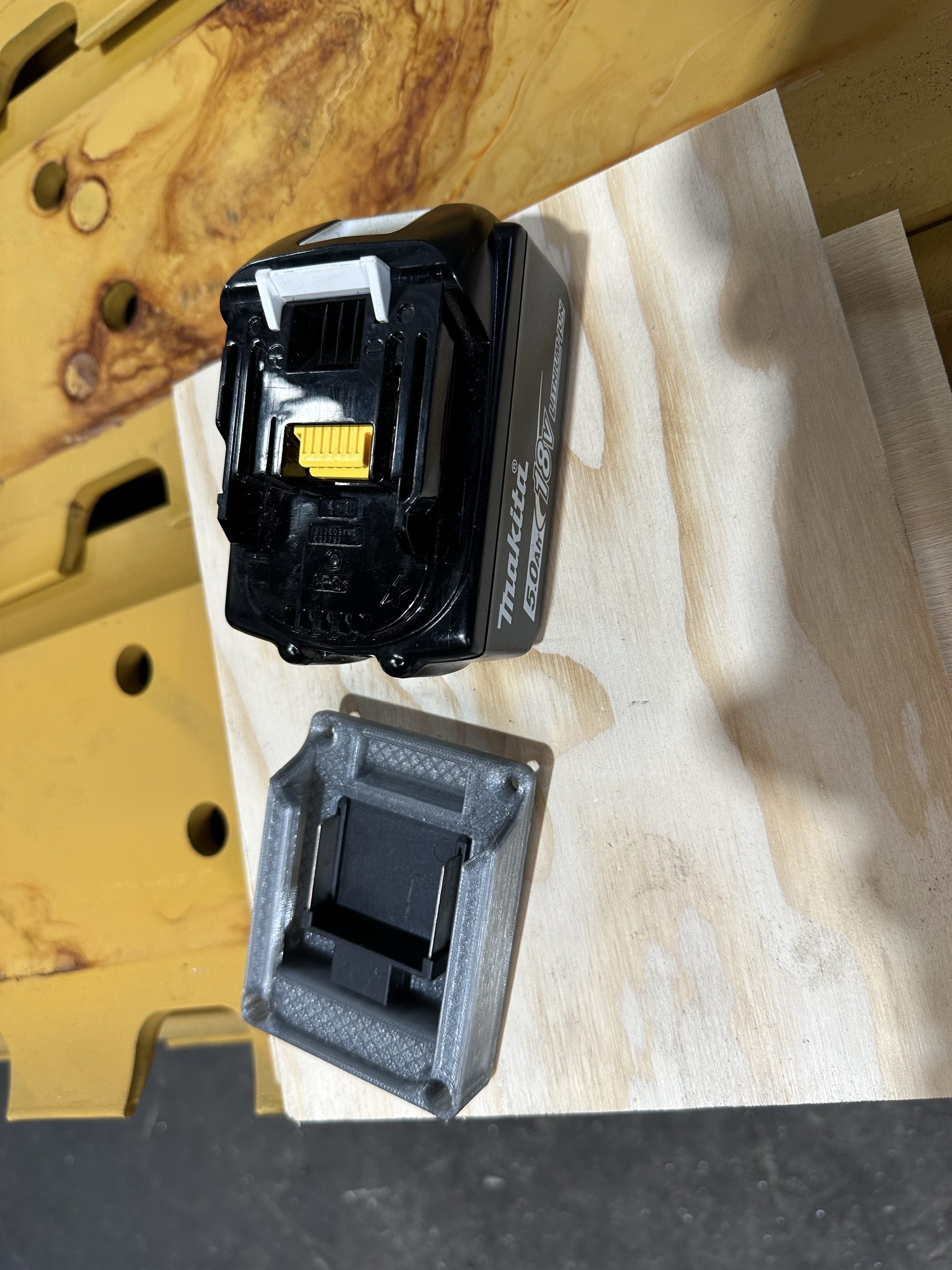
It is powered by (or will have) 2x 2kW motors, 6x 9Ah 18V Makita cordless drill batteries.
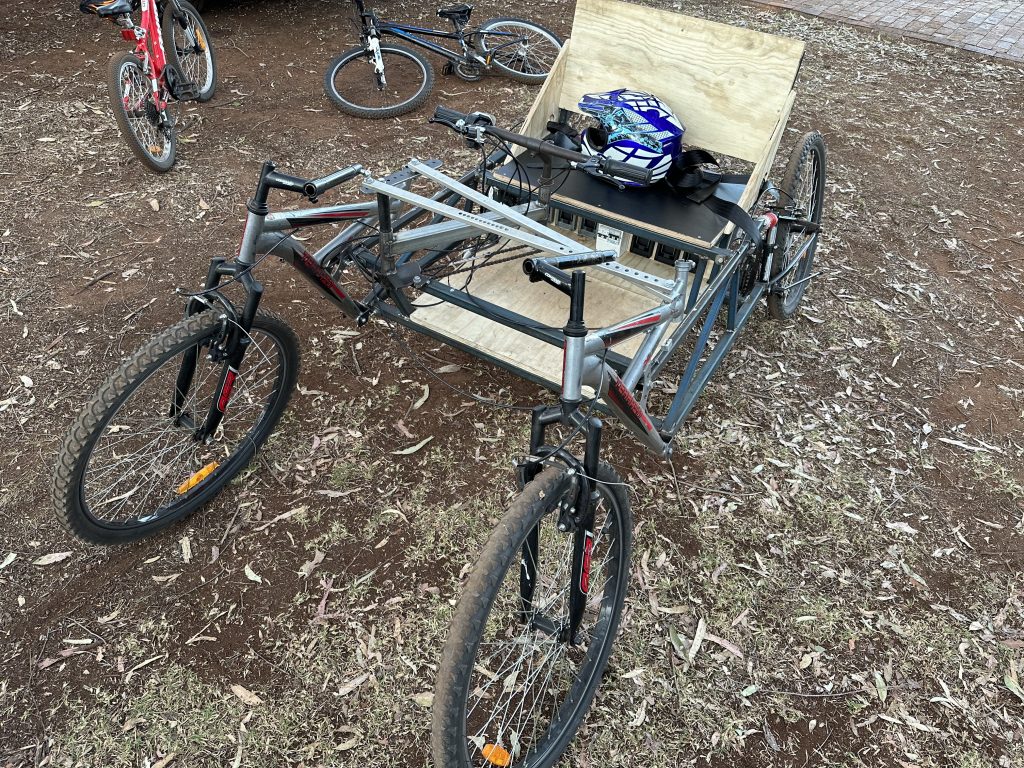
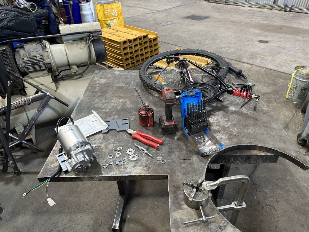
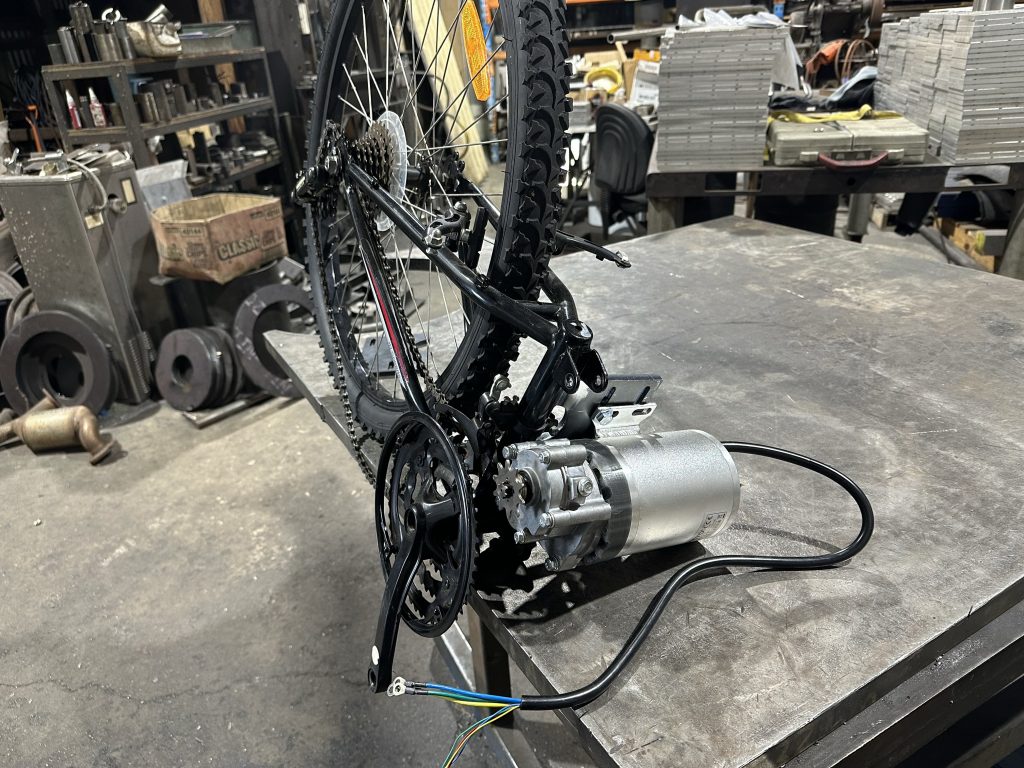
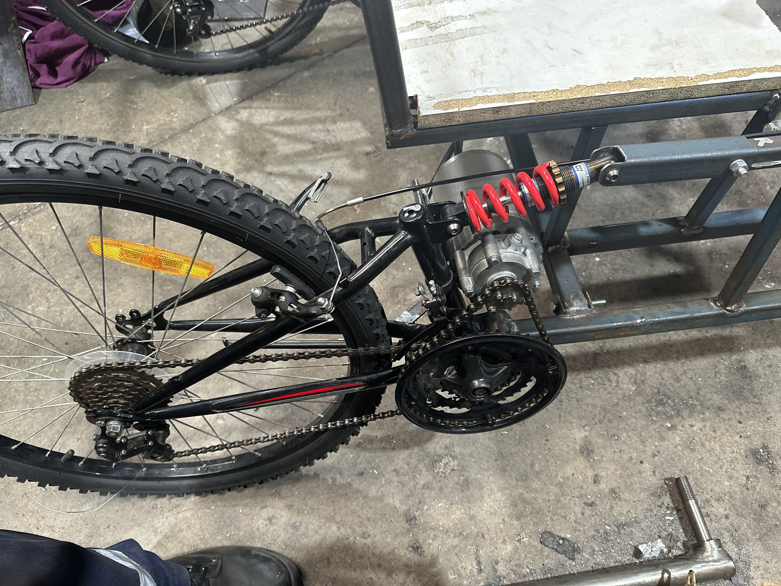
I got 1 motor driving 1 wheel, which has enough power to drive it up the hill, but unfortunately a single driving wheel doesn’t have enough traction up the hill and just spins. I now have the next 12 months to get the second motor installed.
THIS IS STILL BEING WRITTEN SO PLEASE CHECK BACK FOR UPDATES
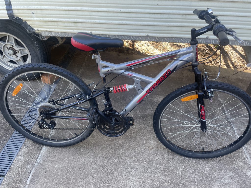
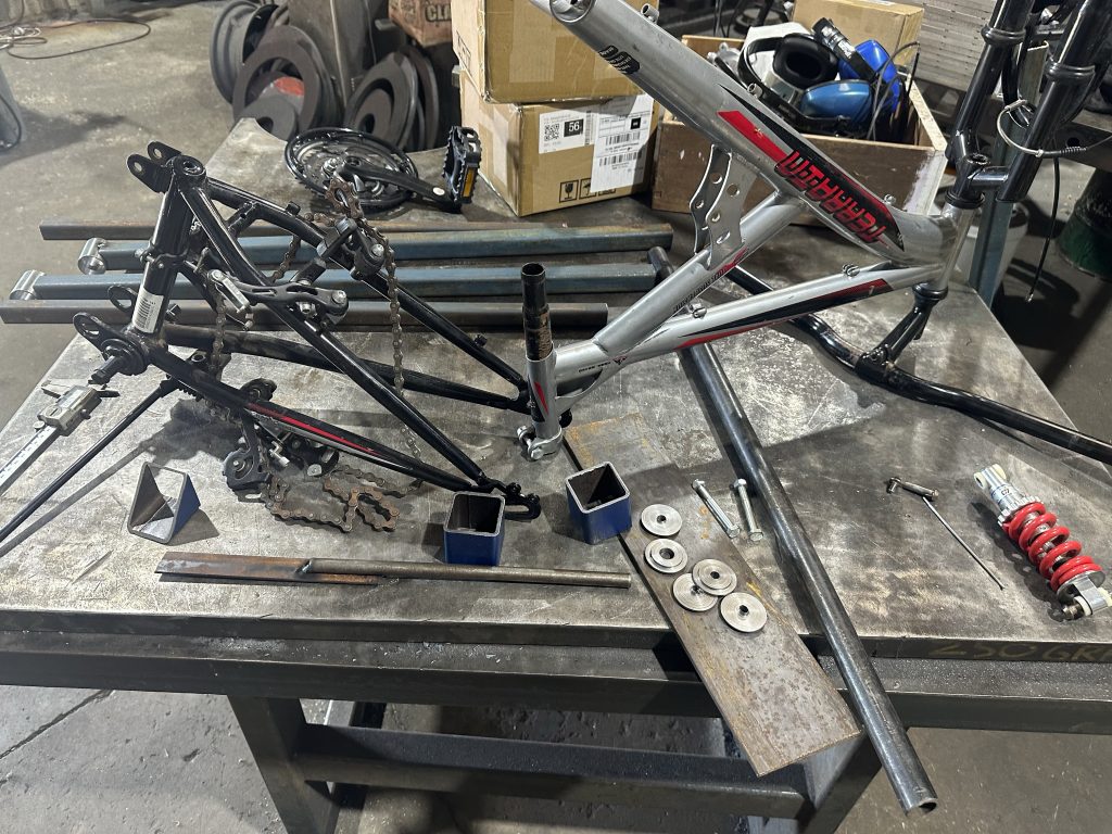
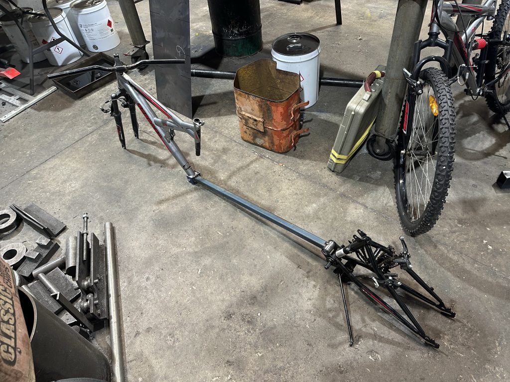
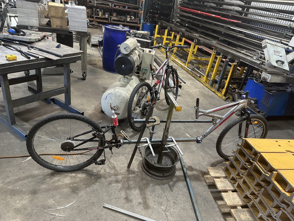
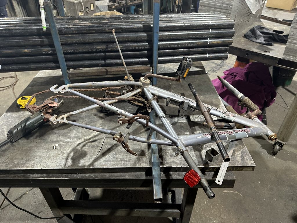
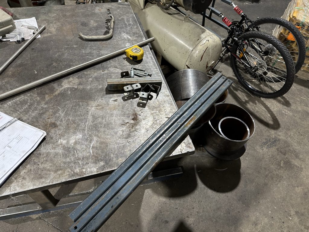
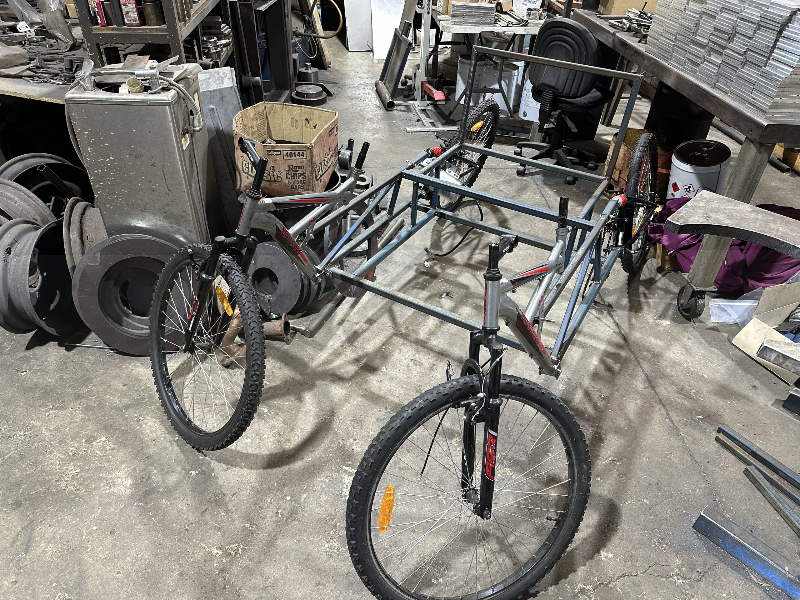
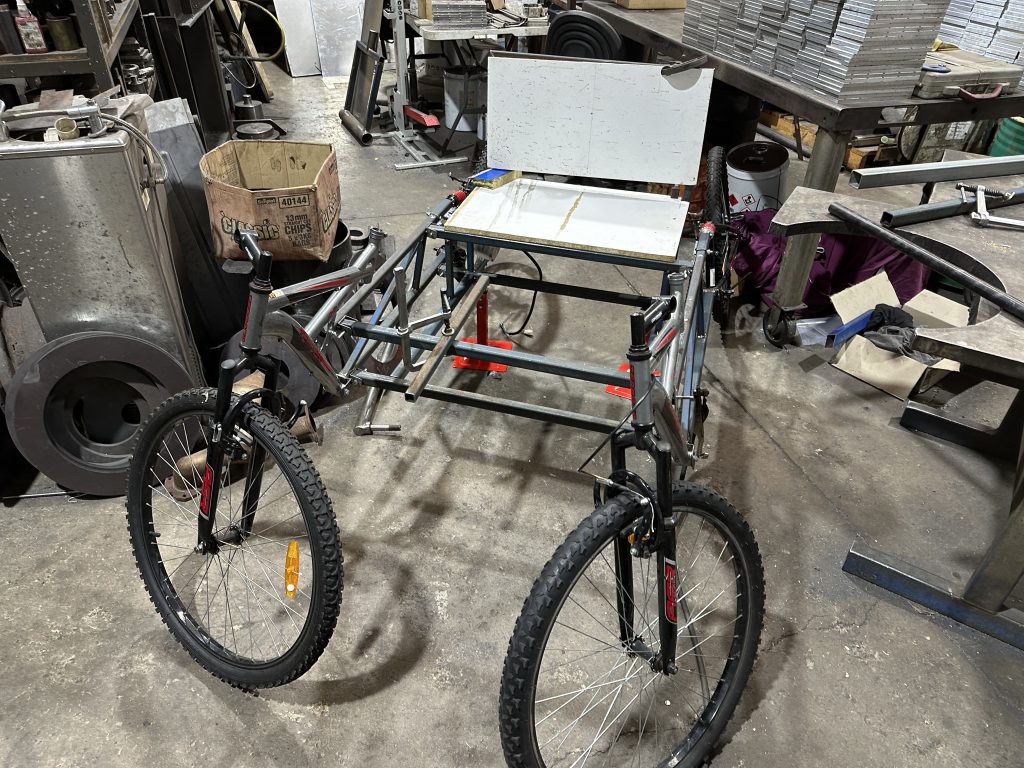
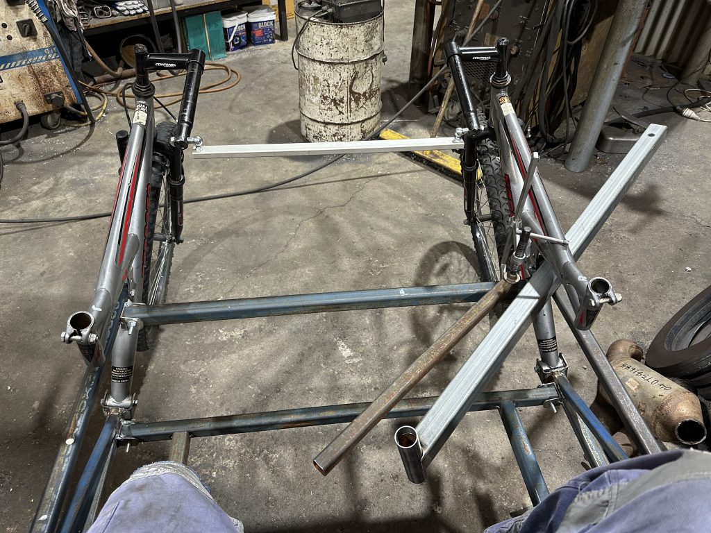
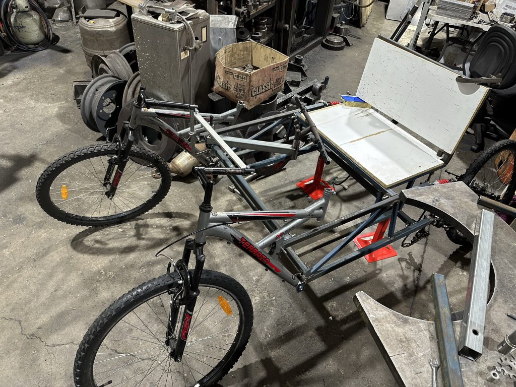
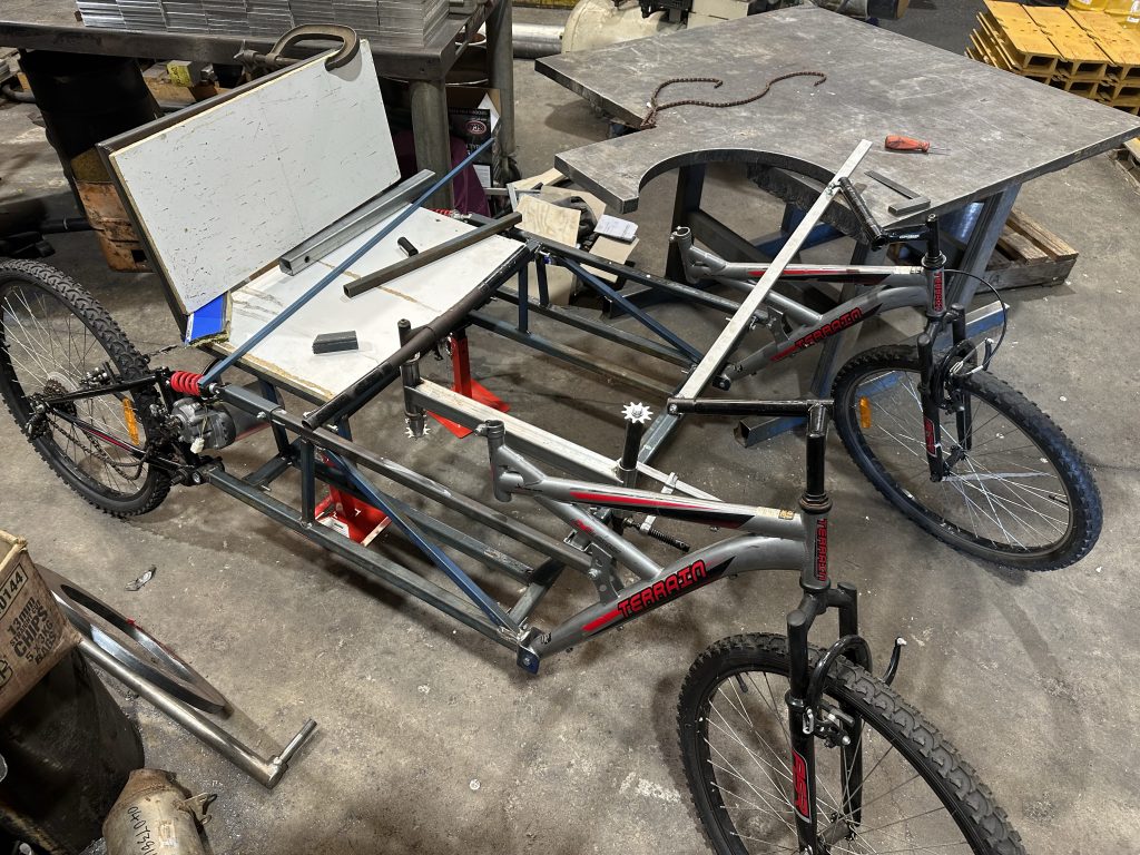
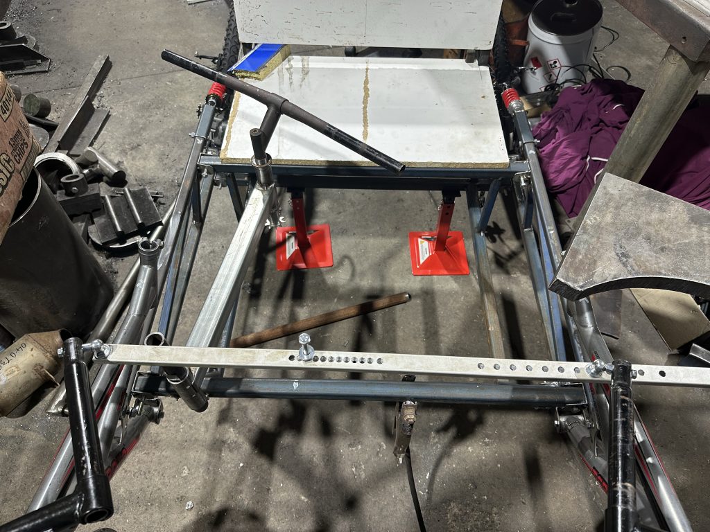
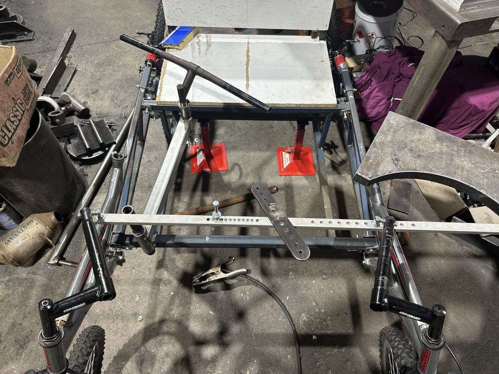
I started off looking for 2 bikes of the same model with dual suspension. The second bike was bit of an issue after the one I found the guy had given it away to someone else so I had search for 6 weeks for another to match the first one I had.
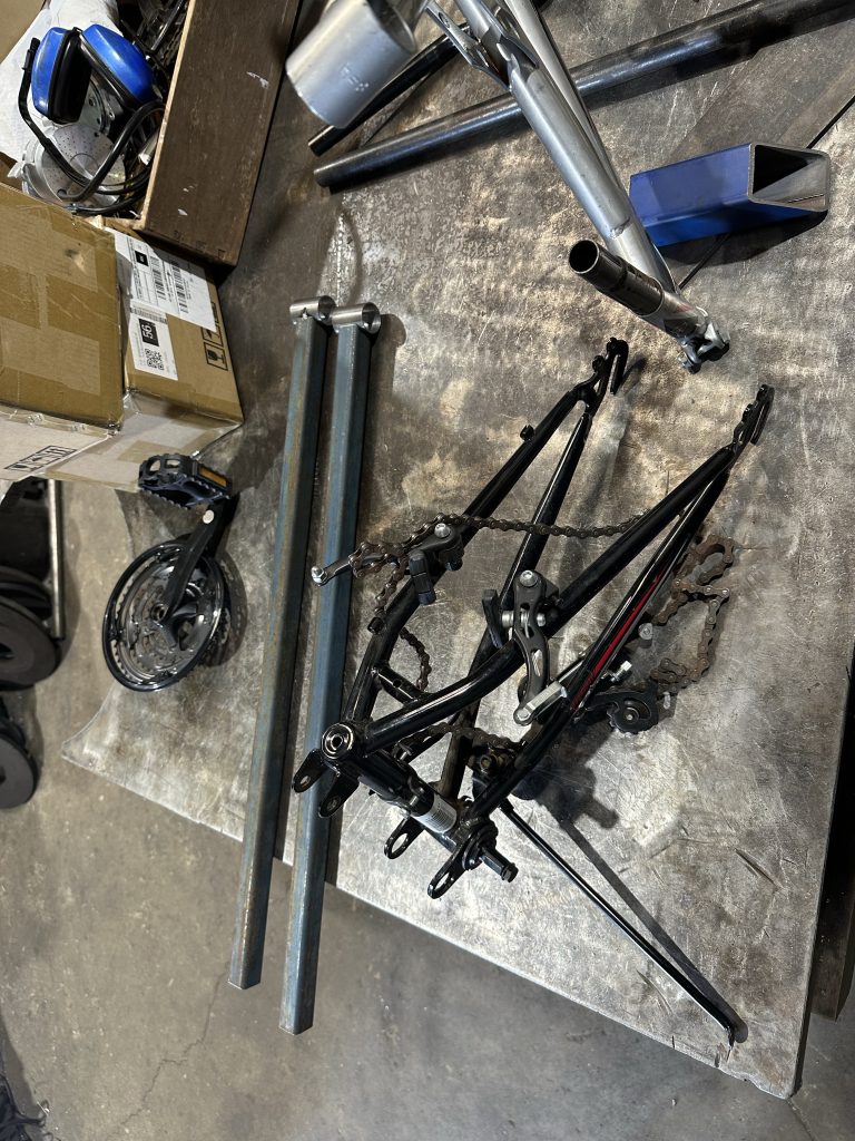
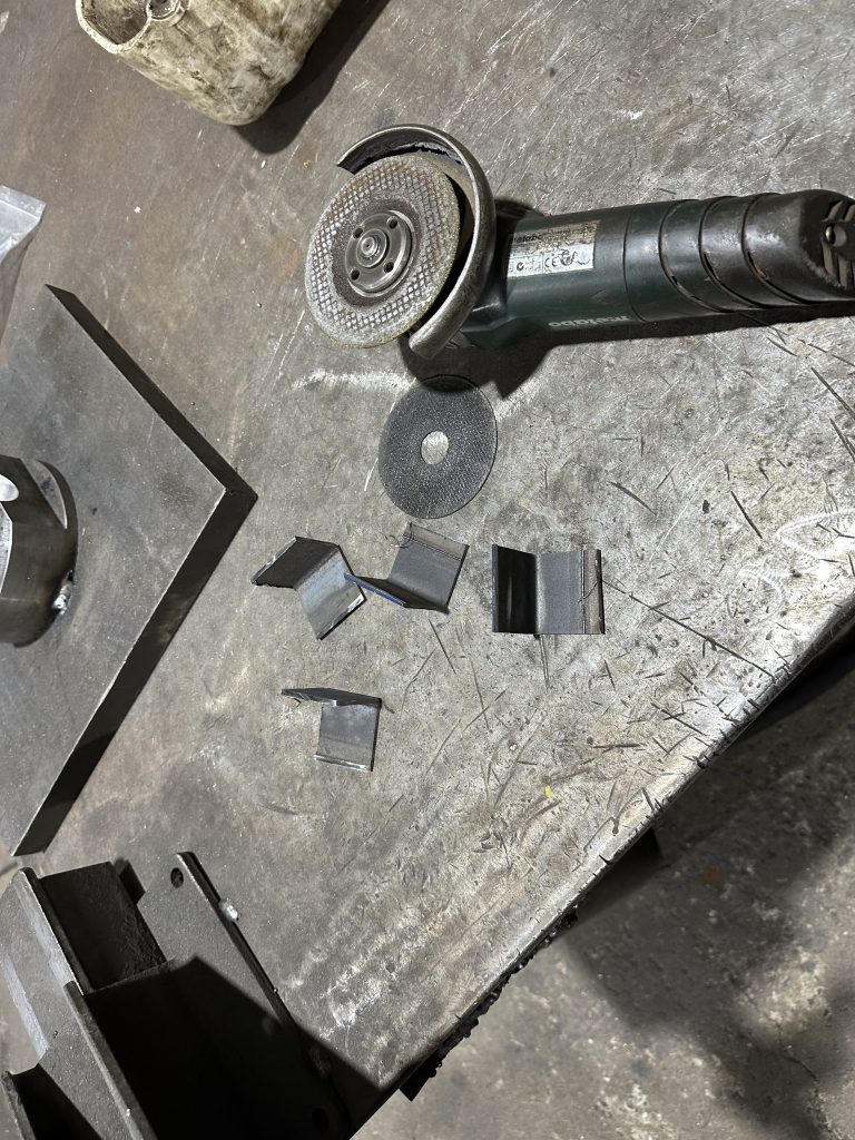
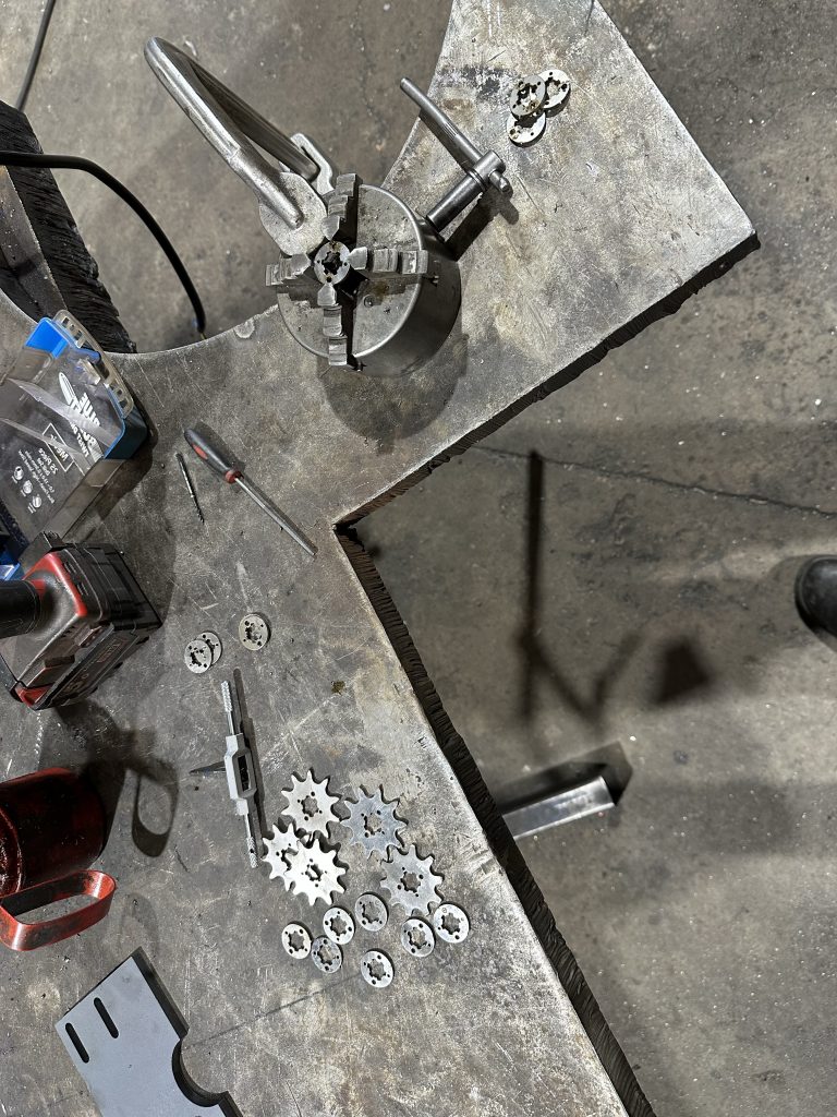
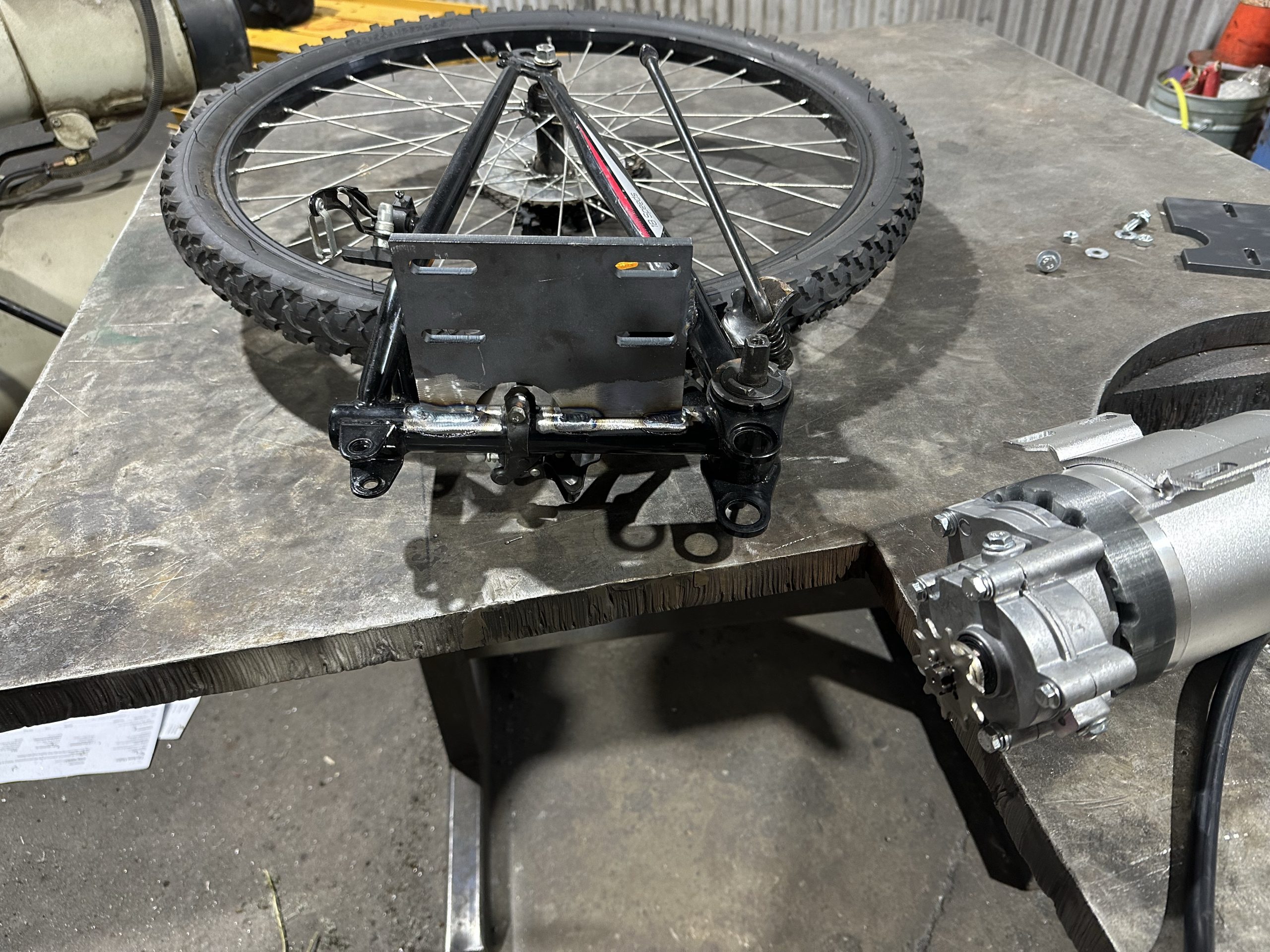
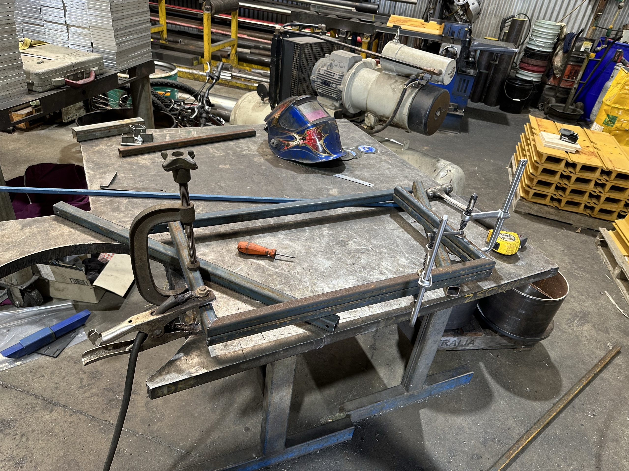
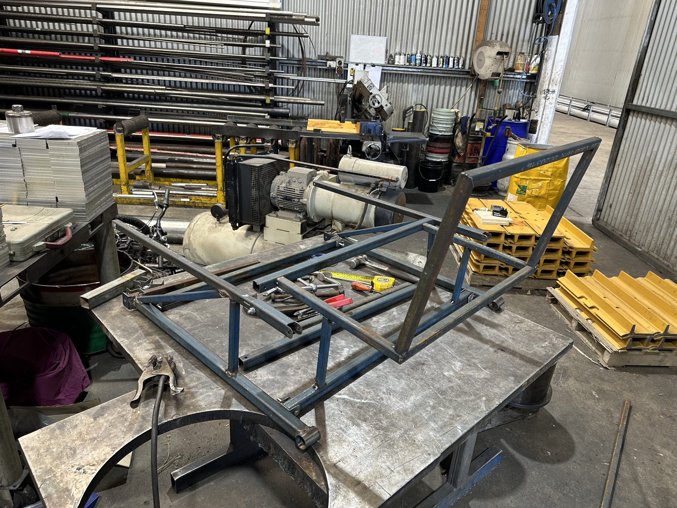
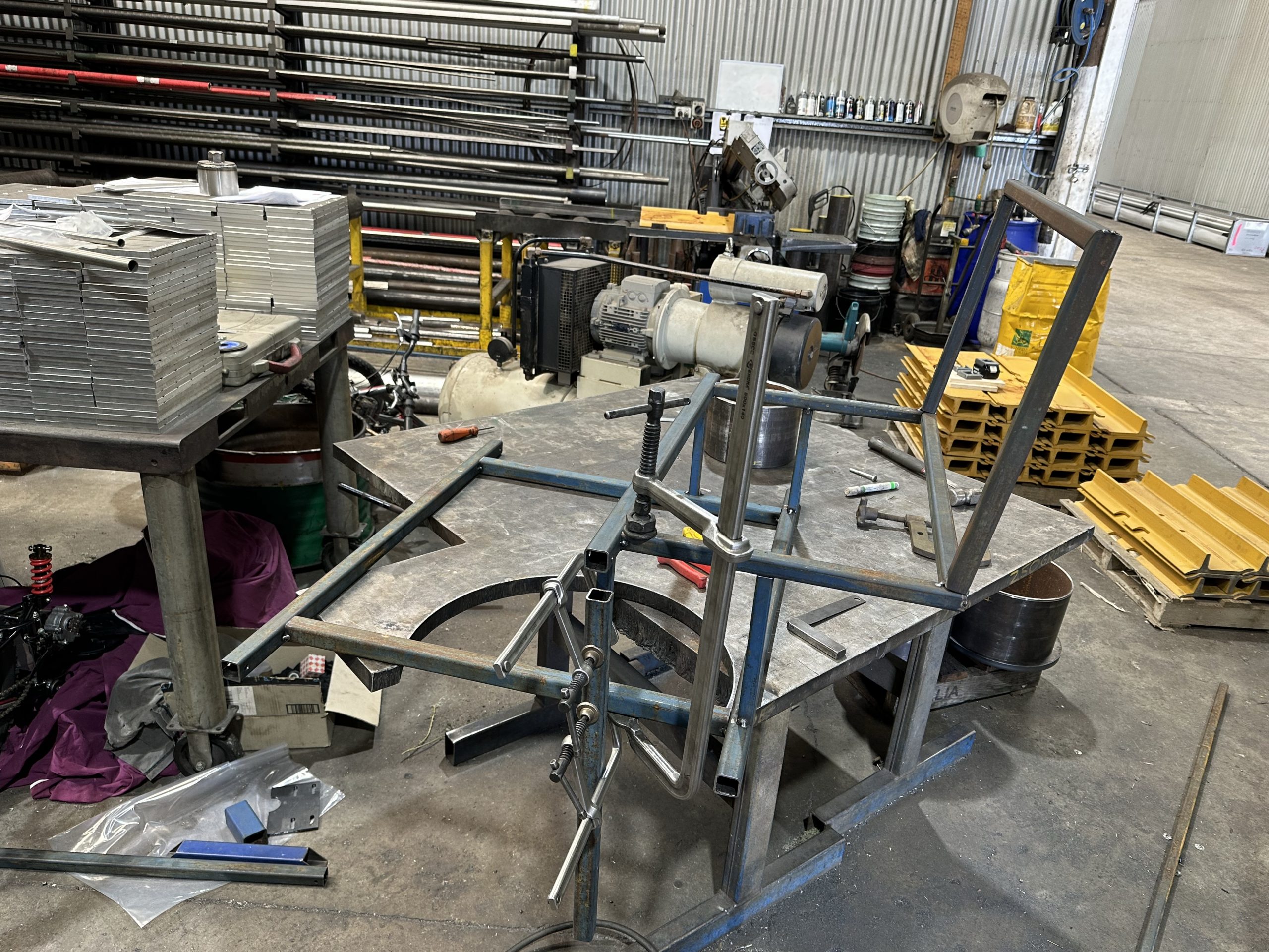
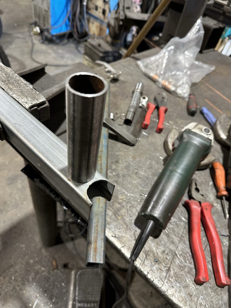
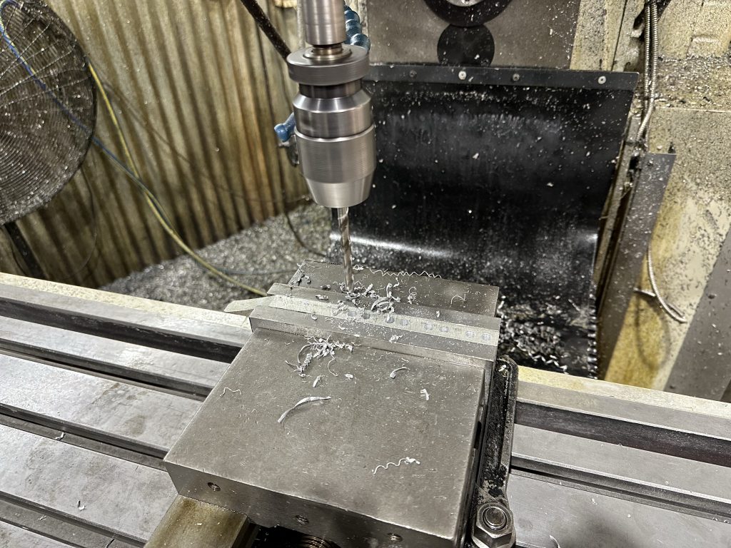
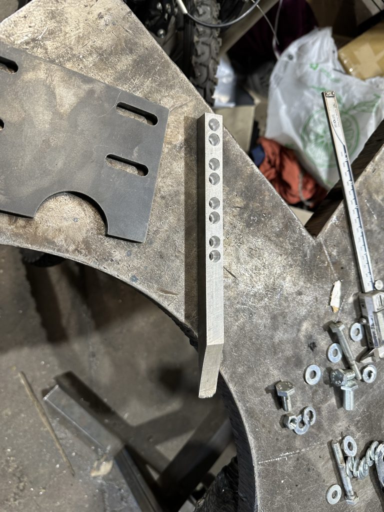
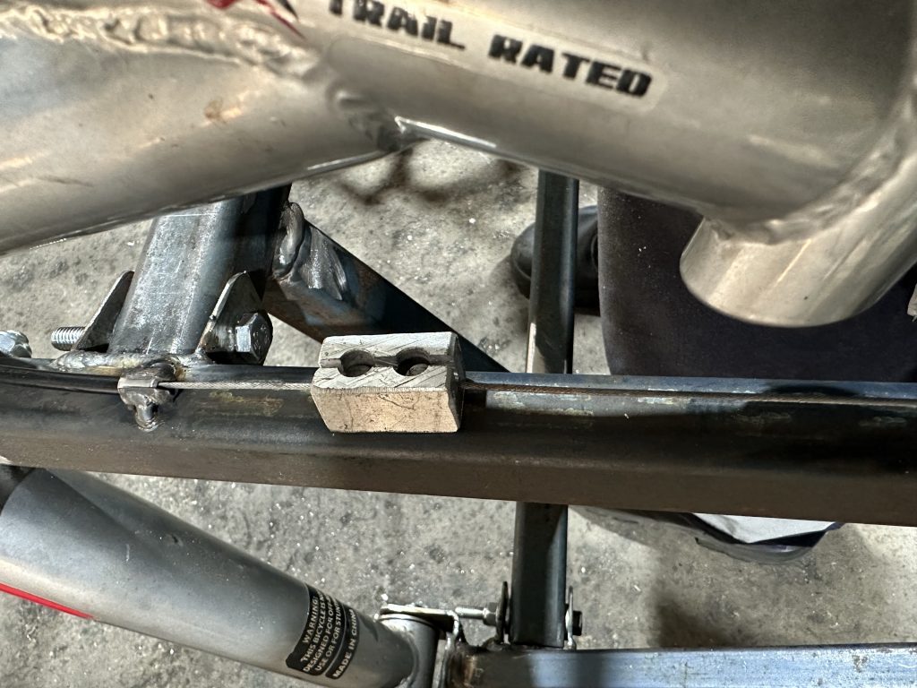
After pulling apart the frame, I made the lower extension arm. My fish mouthing of the end of the RHS was dreadful, but nothing a lot of filler weld couldn’t fix.
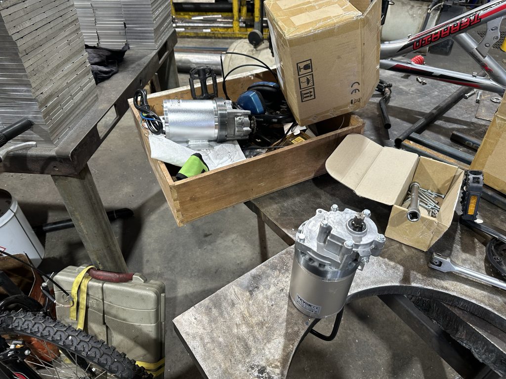
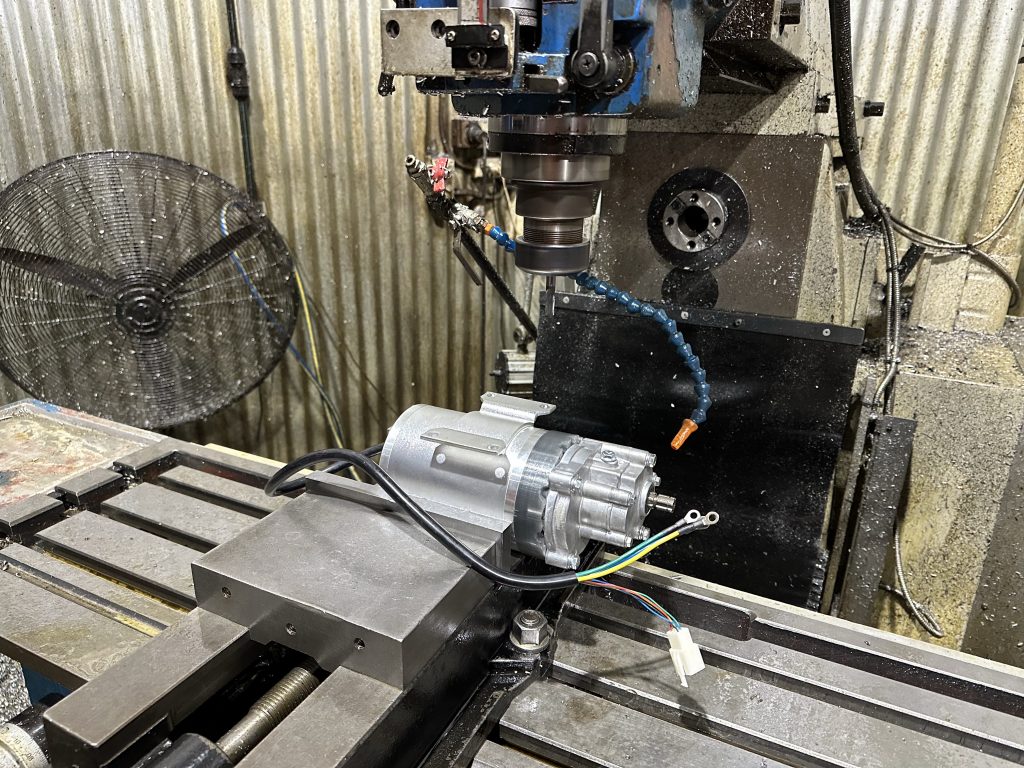
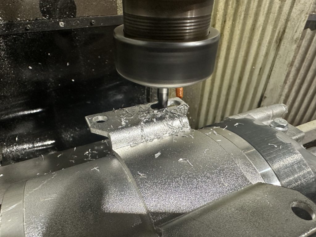
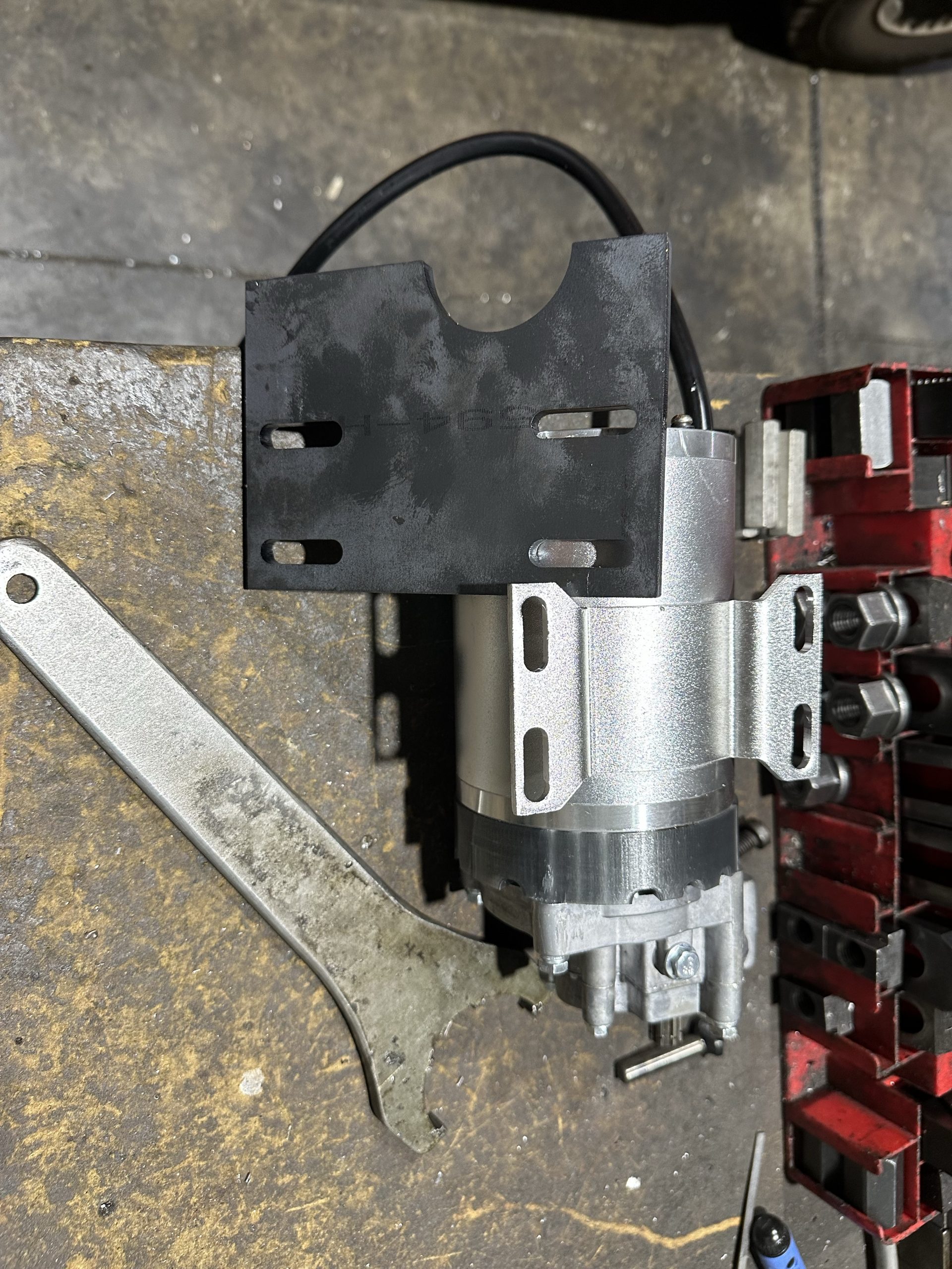
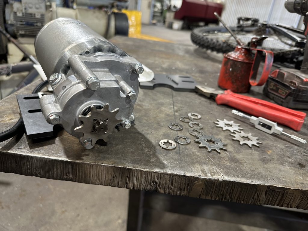
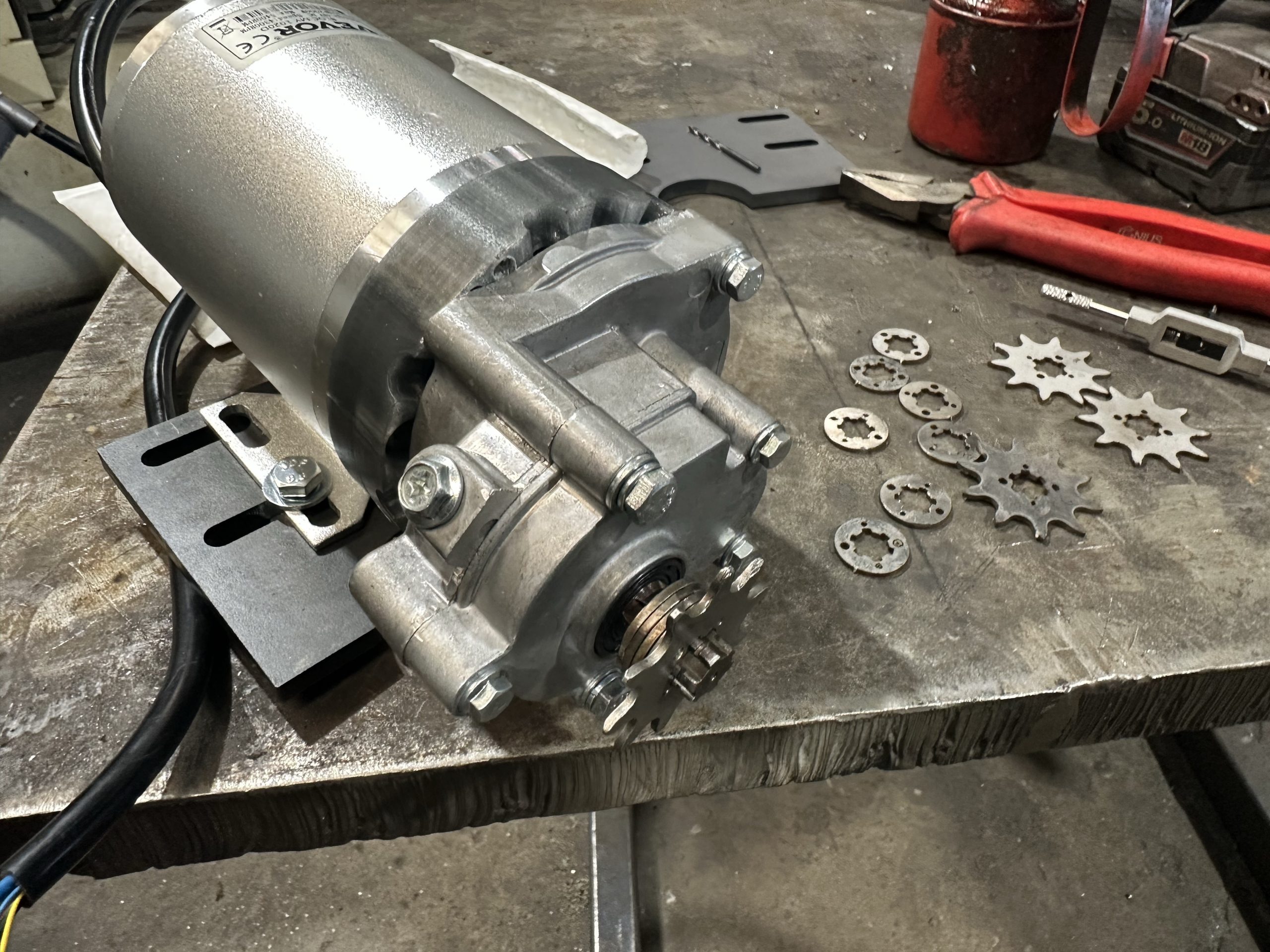
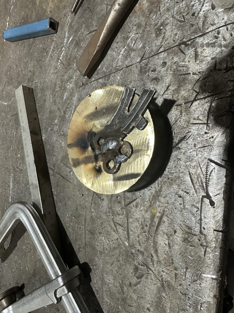
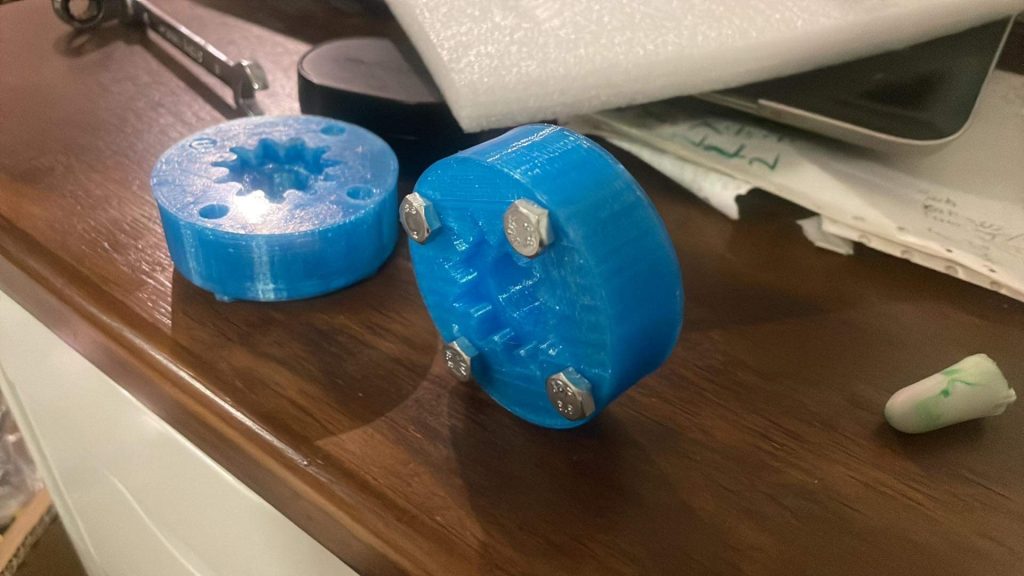
Motor with laser cut mounting plate

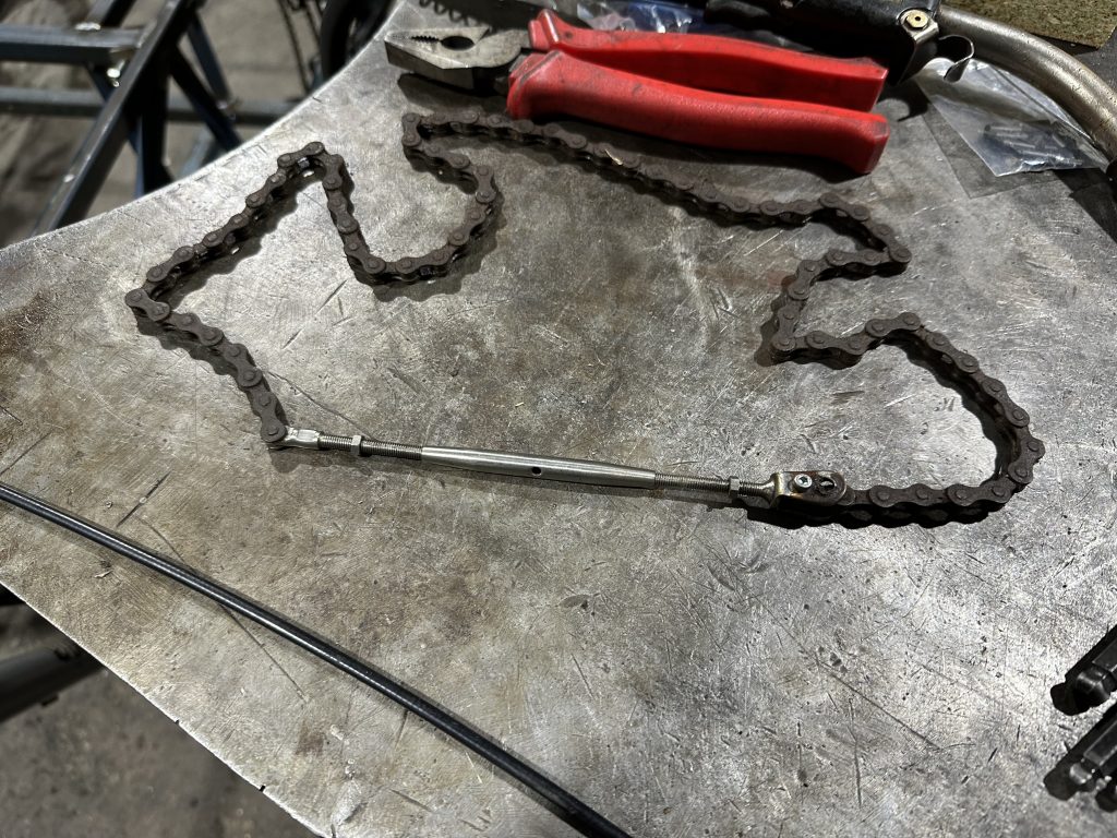
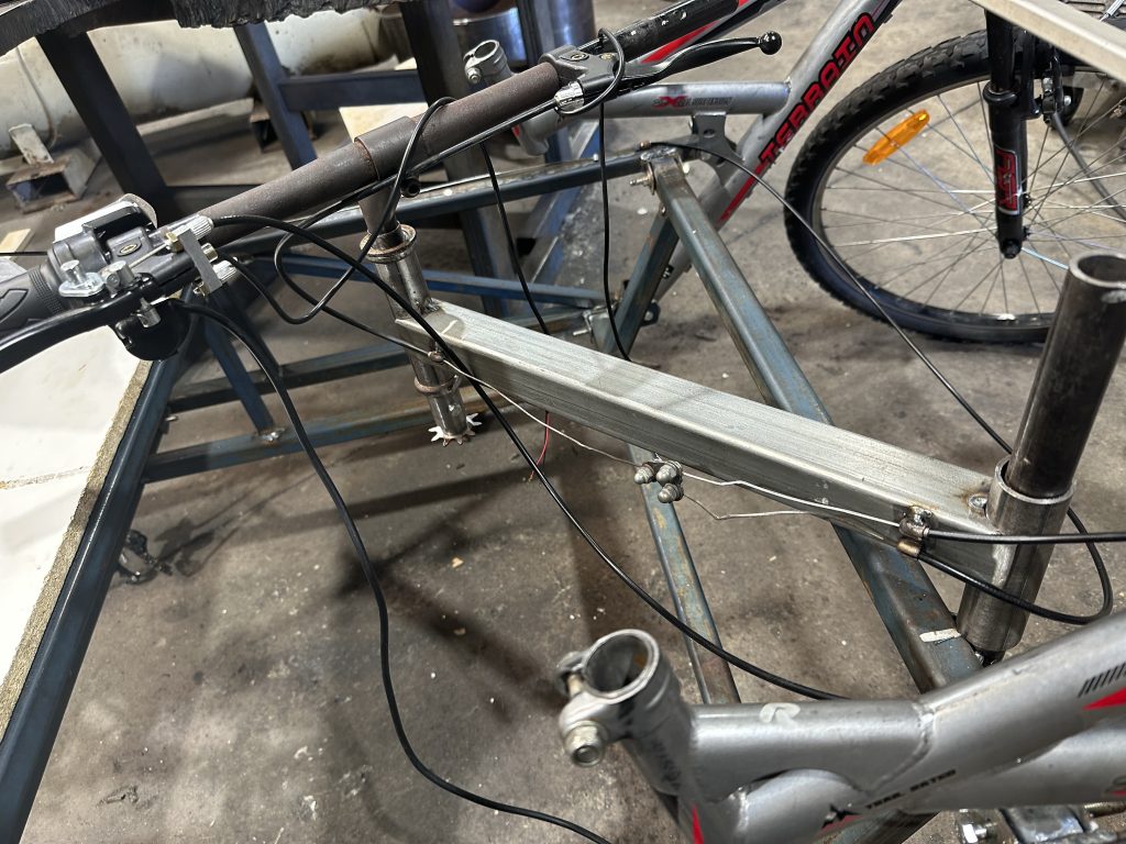
I tried ordering longer brake cables from a local bike shop but unfortunately they didn’t make it in time. So that left me with joining and extending shorter brake cables.
I did do I quick power up test and calculations that running the motor off a slightly higher voltage the inverters would survive. A 12v lead acid battery has a nominal voltage of 12v, and is considered flat at about 10.5v. What we are interested in is the charging voltage. The charging voltage of a lead acid battery is about 14.5V, so the max system voltage would be 4×14.5V=58V. The full charge voltage of a 18V lithium battery is 20.5V, making the system voltage of 3x18V batteries 3×20.5V=61.5V.
This means I am applying about 3.5V more than what it is designed. I did pull the end cover off to see if I could see what the components were rated for but the MOSFETs/transistors are mounted to the case and I couldn’t be bothered pulling them off to get it apart. I did see a SKD502T which is rated for 85V 120A. So hopefully the internal components have had a bit of headroom designed in to cope for this increase in supply voltage. Unfortunately 2 batteries don’t quite meet the low end cutoff voltage of 42V to run it so 3 batteries it is.
The Makita 18V battery low voltage cutoff seems to be 14V from measuring the voltage of the battery when my Makita DUB184 blower cuts out with a genuine battery, which would mean 2.8V per cell inside the battery, which seems a bit low to me. But working off this it would mean the low voltage cut off of 42V would be appropriate. I would personally go as low as 3V/cell which is 15V on the battery to try to give it some more life.
My main concern is the amount of current being drawn from the battery which might be too much. 2000W/42V=47.6A, which may not be a problem if the motor kits are lower power and not as advertised, which may get their own post once I investigate. The website states rated current and voltage as 34Ax48V=1632W, so something doesn’t add up. Maximum current is stated as 42A, so 42Ax48V=2016W input, and assuming there is efficiency losses in the inverter and motor, this will be less.
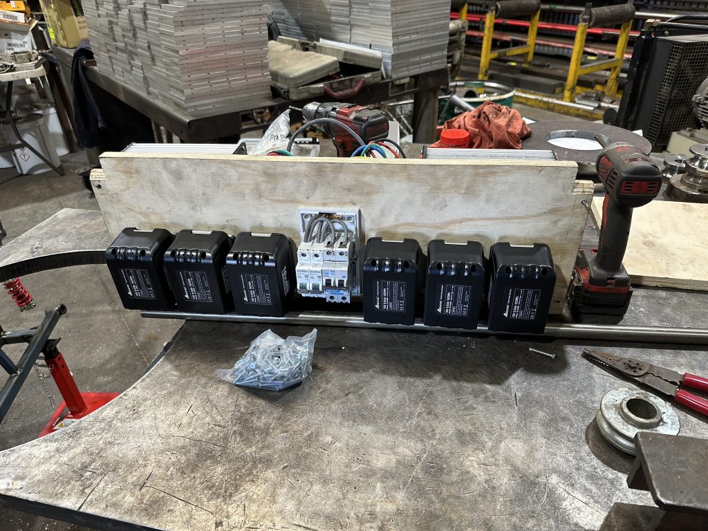
The batteries are set up in 2 groups of 3 in series, with the intent of powering each inverter with 1 set. I have the 0V commoned up between the 2 sets and am only breaking the positive. I was going to put the circuit breaker on positive and negative, but because I am joining signal cables to control both units together I can’t have the 0V on one go open and somehow ground out through another sensor wire. I also have another breaker allowing both battery banks to be paralleled.
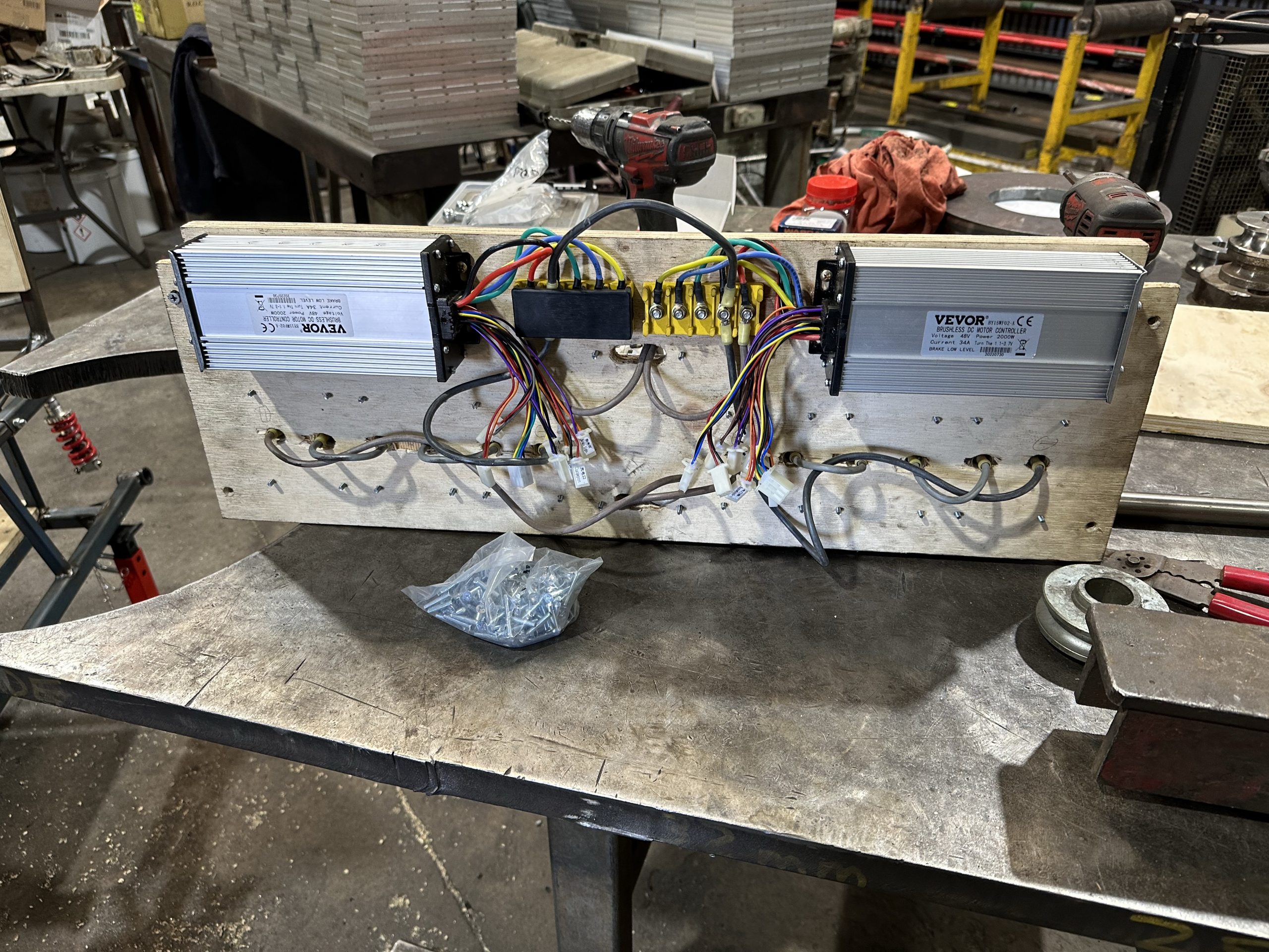
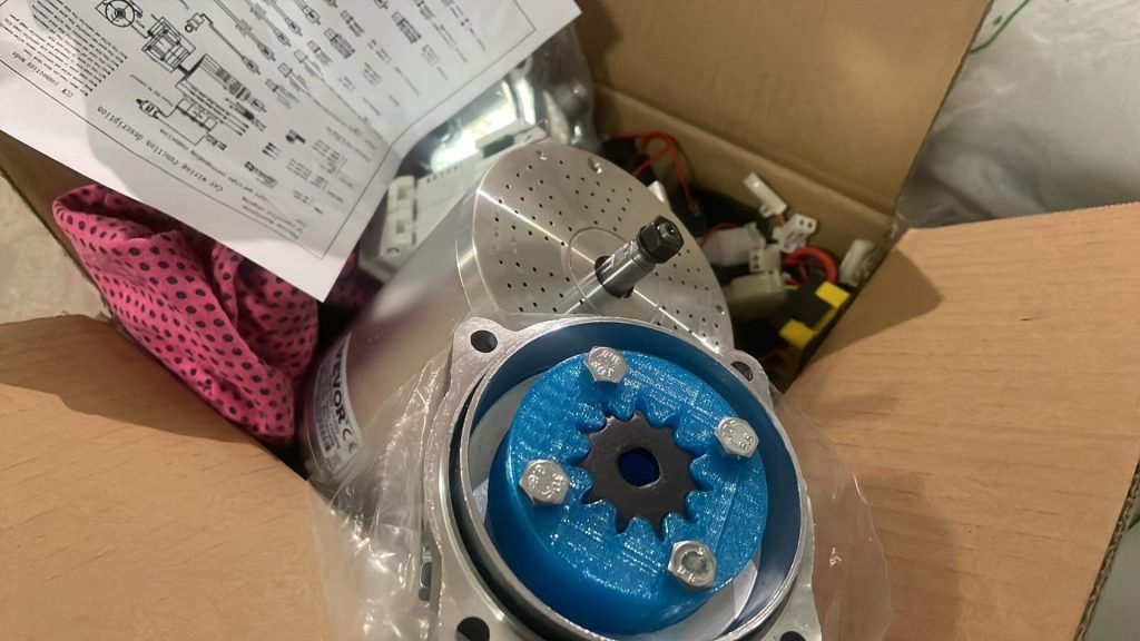
The motor I purchased. I went through eBay but this is the same https://m.vevor.com.au/brushless-dc-motor-c_11227/brushless-motor-go-kart-electric-motor-for-go-kart-48v-2000w-w-controller-p_010581696579
Wish list of improvements/additions
Modify voltmeter on ignition key to display 46V as flat
Make a voltage/current sense circuit to measure voltages of batteries so keeping them as a set is not so important. If batteries of different capacities are connected together in series, the lowest capacity battery voltage goes down fist and can easily be over discharged by the other batteries.
Add wider tyres on the rear for more traction
Better brakes?
Improve steering
Make the cart tilt/pivot the direction turned
Remote kill switch?
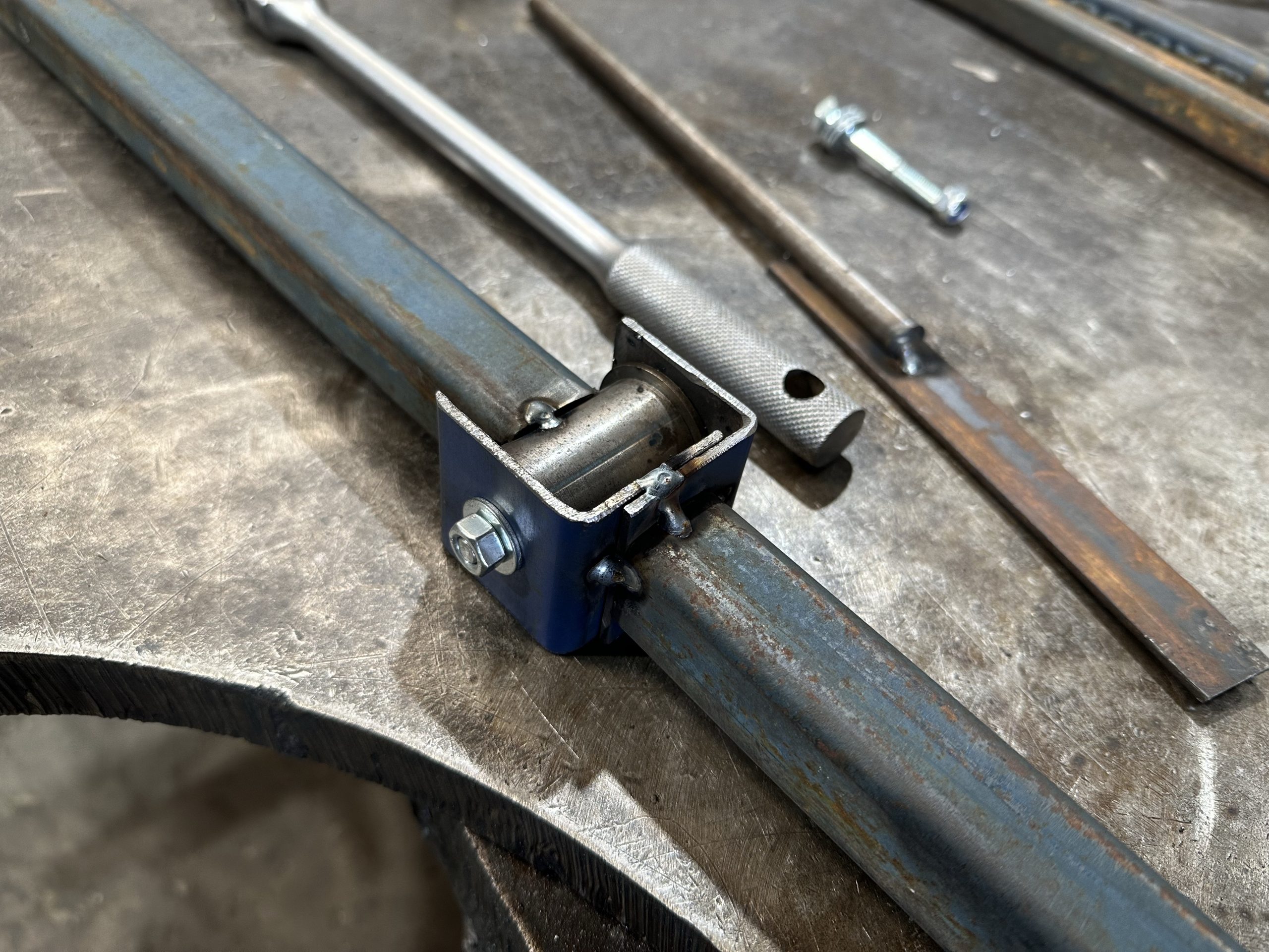
Chain tensioner on motor?
Enable changing of gears?
Brass bushes for rear pivot point to replace the plastic ones